Jeep Cherokee (XJ): Lamp bulb service
REMOVAL AND INSTALLATION
Headlamp bulb
REMOVAL
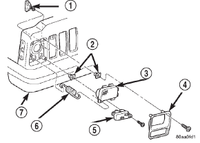
(1) Remove the screws attaching the bezel to the grille opening panel (Fig. 1).
(2) Remove screws attaching the retaining ring to the headlamp canister.
(3) Disconnect the headlamp bulb wire harness connector.
(4) Separate the sealed beam from the vehicle.

Fig. 1 Headlamp Bezel
1 - HEADLAMP ADJUSTMENT
2 - NUT
3 - HEADLAMP
4 - BEZEL
5 - PARK/TURN LAMP
6 - SPRING
7 - BUMPER
INSTALLATION
(1) Connect wire harness connector.
(2) Position bulb in canister.
(3) Position retaining ring on sealed beam and install screws.
(4) Install headlamp bezel.
Fog lamp bulb
REMOVAL
(1) Remove the screws attaching the access cover to the bottom of the fog lamp (Fig. 2).
(2) Remove spring clip securing bulb to fog lamp.
(3) Disconnect bulb wire connector.
(4) Remove bulb element from fog lamp.

Fig. 2 Fog Lamp Components
1 - FOG LAMP
2 - CLIP
3 - BULB
4 - ACCESS COVER
5 - BULB SOCKET
INSTALLATION
CAUTION: Do not touch the bulb glass with fingers or other oily surfaces. Reduced bulb life will result.
(1) Position bulb element in fog lamp.
(2) Connect bulb wire connector.
(3) Install spring clip securing bulb to fog lamp.
(4) Install screws attaching the access cover to the bottom of the fog lamp.
Front park/turn signal lamp bulb
REMOVAL
(1) Remove headlamp bezel.
(2) Remove screws attaching park/turn signal lamp housing to grille opening panel.
(3) Rotate bulb socket one-third turn counter-clockwise and remove it from lamp housing (Fig. 3).
(4) Pull bulb from socket.

Fig. 3 Park/Turn Signal Lamp Bulb
1 - BULB SOCKET
2 - PARK LAMP HOUSING
3 - PARK LAMP BULB
INSTALLATION
(1) Install bulb in socket.
(2) Install socket in lamp housing.
(3) Install park/turn signal lamp housing.
(4) Install headlamp bezel
Side marker lamp bulb
REMOVAL
(1) Remove screws attaching side marker lamp housing.
(2) Rotate bulb socket counter-clockwise and pull from back side of lamp housing (Fig. 4).
(3) Pull bulb from socket.
INSTALLATION
(1) Install bulb in socket.
(2) Install bulb and socket in back of side marker lamp housing.
(3) Install side marker lamp housing.

Fig. 4 Side Marker Lamp
1 - SIDE MARKER LAMP HOUSING
2 - SIDE MARKER LAMP BULB
3 - BULB SOCKET
Back-up/brake/rear turn signal/tail lamp bulb
REMOVAL
(1) Remove tail lamp housing.
(2) Rotate bulb socket one-third turn counter-clockwise and remove bulb socket from lamp housing (Fig.
5).
(3) Pull bulb from socket.

Fig. 5 Bulb Socket Removal
1 - TAIL LAMP BULB
2 - BULB SOCKET
3 - TAIL LAMP HOUSING
INSTALLATION
(1) Install bulb in socket.
(2) Install bulb and socket in lamp housing.
(3) Install lamp housing.
License plate lamp bulb
REMOVAL
(1) Remove screws attaching license plate lamp housing to liftgate.
(2) Rotate bulb socket counter-clockwise and remove bulb socket from lamp housing.
(3) Pull bulb from socket.
INSTALLATION
(1) Install bulb in lamp socket.
(2) Install bulb socket in lamp housing.
(3) Install screws attaching license plate lamp housing to liftgate.
Center high mounted stop lamp (chmsl) bulb
REMOVAL
(1) Remove the screws attaching the lamp housing to the liftgate.
(2) Rotate bulb socket 1/4 turn counter-clockwise and pull from housing (Fig. 6).
(3) Pull bulb from socket.

Fig. 6 CHMSL Bulb
1 - CHMSL BULB
2 - BULB SOCKET
3 - CHMSL LAMP HOUSING
INSTALLATION
(1) Push bulb into socket.
(2) Position socket in lamp and rotate 1/4 turn clockwise.
(3) Install screws attaching lamp housing to the liftgate.
Underhood lamp bulb
REMOVAL
(1) Insert a small flat blade in the access slot between the lamp base and lamp lens.
(2) Pry the lamp lens upward and remove the lamp lens (Fig. 7).
(3) Depress the bulb terminal inward (Fig. 8) to release the bulb.

Fig. 7 Underhood Lamp Lens
1 - LAMP
2 - LAMP LENS

Fig. 8 Underhood Lamp Bulb
1 - BULB
2 - DEPRESS TERMINAL INWARD
3 - BULB WIRE LOOP
4 - LAMP BASE
INSTALLATION
(1) Engage the replacement bulb wire loop to the terminal closest to the lamp base wire connector
(2) Depress the opposite terminal inward and engage the remaining bulb wire loop.
(3) Position the lamp lens on the lamp base and press into place.
Cargo lamp bulb
REMOVAL
(1) Insert a small flat blade into the access slots (Fig. 9).
(2) Carefully pry the lens from the lamp.
(3) Grasp bulb and pull from lamp.

Fig. 9 Cargo Lamp Lens
1 - HOUSING
2 - SCREWDRIVER SLOTS
3 - CARGO LAMP
4 - LENS
INSTALLATION
(1) Position bulb in lamp and snap into place.
(2) Position the lens at the lamp housing and force it upward into the housing until the mounting tabs are seated on the lamp mounting pins.
Map reading lamp bulb
REMOVAL
(1) Insert a flat blade screwdriver in slot at front of lens (Fig. 10).
(2) Rotate the screwdriver until lens snaps out of the housing.
(3) Remove lens from housing.
(4) Remove bulb from terminals.

Fig. 10 Reading Lamp Bulb
1 - LENS
2 - FLAT BLADE
3 - CONSOLE
INSTALLATION
(1) Insert bulb into reading lamp terminals.
(2) Replace lens by holding lens level and pushing rearward into housing.
(3) Push lens up to snap into housing.
Visor vanity lamp bulb
REMOVAL
(1) Using a small flat blade, carefully pry each corner of lens outward from lamp.
(2) Separate lens from lamp.
(3) Grasp bulb and pull outward.
INSTALLATION
(1) Position bulb in socket and push into place.
(2) Position lens on lamp and snap into place.
Other materials:
Hydraulic tappets. Vibration damper. Timing case cover oil seal
Hydraulic tappets
REMOVAL
Retain all the components in the same order as
removed.
(1) Remove the engine cylinder head cover (refer to
procedure earlier in this section)
(2) Remove the bridge and pivot assemblies and
rocker arms by removing the capscrews at each
bridge. Alternately loosen ea ...


