Jeep Cherokee (XJ): Removal and installation
The ASD relay is located in the Power Distribution
Center (PDC) (Fig. 23). Refer to label on PDC cover
for relay location. REMOVAL (1) Remove PDC cover.
(2) Remove relay from PDC.
(3) Check condition of relay terminals and PDC
connector terminals for damage or corrosion. Repair
if necessary before installing relay.
(4) Check for pin height (pin height should be the
same for all terminals within the PDC connector).
Repair if necessary before installing relay. INSTALLATION (1) Install relay to PDC.
(2) Install cover to PDC.
1 - POWER DISTRIBUTION CENTER (PDC) The fuel pump relay is located in the Power Distribution
Center (PDC) (Fig. 23). Refer to label on PDC
cover for relay location. REMOVAL (1) Remove PDC cover.
(2) Remove relay from PDC.
(3) Check condition of relay terminals and PDC
connector terminals for damage or corrosion. Repair
if necessary before installing relay.
(4) Check for pin height (pin height should be the
same for all terminals within the PDC connector).
Repair if necessary before installing relay. INSTALLATION (1) Install relay to PDC.
(2) Install cover to PDC. A (factory adjusted) set screw is used to mechanically
limit the position of the throttle body throttle
plate. Never attempt to adjust the engine idle
speed using this screw. All idle speed functions are
controlled by the Powertrain Control Module (PCM). REMOVAL (1) Remove air cleaner tube at throttle body.
(2) Disconnect throttle body electrical connectors
at MAP sensor, IAC motor and TPS (Fig. 24) or (Fig.
25).
1 - MOUNTING BOLTS (4) (3) Remove all control cables from throttle body
(lever) arm. Refer to the Accelerator Pedal and Throttle
Cable section of this group for additional information.
(4) Remove four throttle body mounting bolts.
(5) Remove throttle body from intake manifold.
(6) Discard old throttle body-to-intake manifold
gasket. INSTALLATION (1) Clean mating surfaces of throttle body and
intake manifold.
(2) Install new throttle body-to-intake manifold
gasket.
(3) Install throttle body to intake manifold.
(4) Install four mounting bolts. Tighten bolts to 11
N·m (100 in. lbs.) torque.
(5) Install control cables.
(6) Install electrical connectors.
(7) Install air cleaner at throttle body.
1 - IDLE AIR CONTROL MOTOR The TPS is mounted to the throttle body (Fig. 24)
or (Fig. 25). REMOVAL (1) Remove air cleaner tube at throttle body.
(2) Disconnect TPS electrical connector.
(3) Remove TPS mounting screws (Fig. 26).
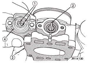
(4) Remove TPS. INSTALLATION The throttle shaft end of the throttle body slides
into a socket in the TPS (Fig. 27). The TPS must be
installed so that it can be rotated a few degrees. (If
the sensor will not rotate, install the sensor with the
throttle shaft on the other side of the socket tangs).
The TPS will be under slight tension when rotated.
(1) Install TPS and retaining screws.
(2) Tighten screws to 7 N·m (60 in. lbs.) torque.
(3) Connect TPS electrical connector to TPS.
(4) Manually operate throttle (by hand) to check
for any TPS binding before starting engine.
(5) Install air cleaner tube to throttle body. The IAC motor is located on the side of the throttle
body (Fig. 24) or (Fig. 25).
1 - MOUNTING SCREWS
1 - TANGS REMOVAL (1) Remove air cleaner tube at throttle body.
(2) Disconnect electrical connector from IAC motor.
(3) Remove two mounting bolts (screws) (Fig. 28).
(4) Remove IAC motor from throttle body. INSTALLATION (1) Install IAC motor to throttle body.
(2) Install and tighten two mounting bolts (screws)
to 7 N·m (60 in. lbs.) torque.
(3) Install electrical connector.
(4) Install air cleaner tube to throttle body.
1 - IDLE AIR CONTROL MOTOR The MAP sensor is mounted to the side of the
throttle body (Fig. 24) or (Fig. 25). An L-shaped rubber
fitting is used to connect the MAP sensor to
throttle body (Fig. 29).
1 - THROTTLE BODY REMOVAL (1) Remove air cleaner intake tube at throttle
body.
(2) Remove two MAP sensor mounting bolts
(screws) (Fig. 29).
(3) While removing MAP sensor, slide the rubber
L-shaped fitting (Fig. 29) from throttle body.
(4) Remove rubber L-shaped fitting from MAP sensor. INSTALLATION (1) Install rubber L-shaped fitting to MAP sensor.
(2) Position sensor to throttle body while guiding
rubber fitting over throttle body vacuum nipple.
(3) Install MAP sensor mounting bolts (screws).
Tighten screws to 3 N·m (25 in. lbs.) torque.
(4) Install air cleaner intake tube. The PCM is located in the engine compartment
next to the air cleaner assembly (Fig. 30).
1 - (3) 32-WAY CONNECTORS REMOVAL To avoid possible voltage spike damage to the
PCM, ignition key must be off, and negative battery
cable must be disconnected before unplugging PCM
connectors.
(1) Disconnect negative battery cable at battery.
(2) Remove cover over electrical connectors. Cover
snaps onto PCM.
(3) Carefully unplug the three 32-way connectors
(Fig. 31) from PCM.
(4) Remove three PCM mounting bolts and remove
PCM from vehicle. INSTALLATION (1) Install PCM and mounting bolts to vehicle.
(2) Tighten bolts to 4 N·m (35 in. lbs.).
(3) Check pin connectors in the PCM and the three
32-way connectors for corrosion or damage. Also, the
pin heights in connectors should all be same. Repair
as necessary before installing connectors.
1 - PCM (4) Install three 32-way connectors.
(5) Install cover over electrical connectors. Cover
snaps onto PCM.
(6) Install battery cable.
(7) Use the DRB scan tool to reprogram new PCM
with vehicles original Identification Number (VIN)
and original vehicle mileage. This switch is not used with 4.0L six-cylinder
engines.
The power steering pressure switch is installed in
the power steering high-pressure hose (Fig. 32). REMOVAL (1) Disconnect electrical connector from power
steering pressure switch.
(2) Place a small container or shop towel beneath
switch to collect any excess fluid.
(3) Remove switch. Use back-up wrench on power
steering line to prevent line bending INSTALLATION (1) Install power steering switch into power steering
line.
(2) Tighten to 14-22 N·m (124-195 in. lbs.) torque.
(3) Connect electrical connector to switch.
(4) Check power steering fluid and add as necessary.
1 - POWER STEERING PRESSURE SWITCH (5) Start engine and again check power steering
fluid. Add fluid if necessary. REMOVAL Never apply any type of grease to the oxygen
sensor electrical connector, or attempt any soldering
of the sensor wiring harness. For sensor
operation, it must have a comparison source of
oxygen from outside the exhaust system. This
fresh air is supplied to the sensor through its
pigtail wiring harness.
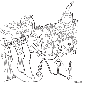
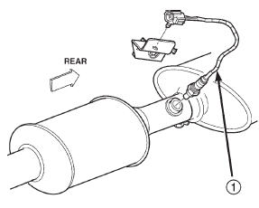
Refer to (Fig. 33), (Fig. 34), (Fig. 35) or (Fig. 36) for
O2S (oxygen sensor) location. WARNING: THE EXHAUST MANIFOLD, EXHAUST
PIPES AND CATALYTIC CONVERTER BECOME
VERY HOT DURING ENGINE OPERATION. ALLOW
ENGINE TO COOL BEFORE REMOVING OXYGEN
SENSOR.
(1) Raise and support vehicle.
(2) Disconnect wire connector from O2S sensor. CAUTION: When disconnecting sensor electrical
connector, do not pull directly on wire going into
sensor.
(3) Remove O2S sensor with an oxygen sensor
removal and installation tool.
(4) Clean threads in exhaust pipe using appropriate
tap.
1 - 1/1 O2S
1 - 1/1 O2S
1 - 1/1 O2S
1 - 1/2 O2S INSTALLATION Threads of new oxygen sensors are factory coated
with anti-seize compound to aid in removal. DO
NOT add any additional anti-seize compound to
threads of a new oxygen sensor. (1) Install O2S sensor. Tighten to 30 N·m (22 ft.
lbs.) torque.
(2) Connect O2S sensor wire connector.
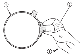
(3) Lower vehicle. REMOVAL (1) Unlock air tube clamp (Fig. 37) at air cleaner
cover. To unlock clamp, attach adjustable pliers to
clamp and rotate pliers as shown in (Fig. 38).
(2) Remove air tube at cover.
(3) Pry back three clips retaining air cleaner cover
to air cleaner housing.
(4) Remove housing cover and remove air cleaner
element.
(5) Clean inside of housing before replacing element.
1 - COVER INSTALLATION (1) Install air cleaner element into housing.
(2) Install air cleaner cover to housing (three
clips). Be sure cover is properly seated to air cleaner
housing.
(3) Install air tube and clamp to cover. Compress
clamp snugly with adjustable pliers as shown in (Fig.
39).
1 - CLAMP
1 - CLAMP WARNING: HOT, PRESSURIZED COOLANT CAN
CAUSE INJURY BY SCALDING. COOLING SYSTEM
MUST BE PARTIALLY DRAINED BEFORE REMOVING
THE COOLANT TEMPERATURE SENSOR.
REFER TO GROUP 7, COOLING.
The coolant temperature sensor is installed in the
thermostat housing (Fig. 40). REMOVAL (1) Partially drain cooling system until coolant
level is below cylinder head. Observe the WARNINGS
in Group 7, Cooling.
1 - THERMOSTAT (2) Disconnect coolant temperature sensor wire
connector.
(3) Remove sensor from thermostat housing. INSTALLATION (1) Apply sealant to sensor threads (new replacement
sensors will have sealant already applied).
(2) Install coolant temperature sensor into thermostat
housing. Tighten to 11 N·m (8 ft. lbs.) torque.
(3) Connect wire connector.
(4) Fill cooling system. Refer to Group 7, Cooling
System. The intake manifold air temperature (IAT) sensor
is installed into intake manifold plenum near throttle
body (Fig. 41) or (Fig. 42). REMOVAL (1) Disconnect electrical connector from IAT sensor.
(2) Remove sensor from intake manifold. INSTALLATION (1) Install IAT sensor into intake manifold.
Tighten sensor to 28 N·m (20 ft. lbs.) torque.
(2) Connect electrical connector to sensor.
1 - MOUNTING BOLTS (4)
1 - ELECTRICAL CONNECTOR The Vehicle Speed Sensor (VSS) is located on the
speedometer pinion gear adapter. If equipped with
4WD, this adapter is located on the transfer case
extension (left side) (Fig. 43). If equipped with 2WD,
this adapter is located on the extension housing of
the transmission (left side).
1 - SENSOR ELECTRICAL CONNECTOR REMOVAL (1) Raise and support vehicle.
(2) Disconnect electrical connector from sensor by
pushing slide tab (Fig. 43). After slide tab has been
positioned, push in on secondary release lock (Fig. 43)
on side of connector and pull connector from sensor.
(3) Remove sensor mounting bolt (Fig. 44).
(4) Remove sensor (pull straight out) from speedometer
pinion gear adapter (Fig. 44). Do not remove
gear adapter from transmission. INSTALLATION (1) Clean inside of speedometer pinion gear
adapter before installing speed sensor.
(2) Install sensor into speedometer gear adapter
and install mounting bolt. Before tightening bolt,
verify speed sensor is fully seated (mounted
flush) to speedometer pinion gear adapter.
(3) Tighten sensor mounting bolt to 2.2 N·m (20 in.
lbs.) torque.
(4) Connect electrical connector to sensor.
1 - ELECTRICAL CONNECTORAutomatic shutdown (asd) relay

Fig. 23 Power Distribution Center (PDC)Fuel pump relay
Throttle body

Fig. 24 Throttle Body and Sensor Locations-4.0L Engine
2 - THROTTLE BODY
3 - IAC MOTOR
4 - ELEC. CONN.
5 - TPS
6 - MAP SENSOR
7 - ELEC. CONN.
8 - IAT SENSOR
9 - ELEC. CONN.
Fig. 25 Throttle Body and Sensor Locations-2.5L Engine
2 - IAT SENSOR
3 - THROTTLE BODY
4 - THROTTLE POSITION SENSOR
5 - MAP SENSOR
6 - IDLE AIR CONTROL PASSAGE INLET
7 - THROTTLE BODY MOUNTING BOLTS (4)Throttle position sensor (TPS)
Idle air control (IAC) motor

Fig. 26 TPS Mounting Screws
2 - TPS
Fig. 27 Throttle Position Sensor-Installation
2 - THROTTLE SHAFT
3 - THROTTLE BODY
4 - TPS
Fig. 28 Mounting Bolts (Screws)-IAC Motor
2 - MOUNTING SCREWSManifold absolute pressure (map)
sensor

Fig. 29 MAP Sensor Mounting
2 - MAP SENSOR
3 - RUBBER FITTING
4 - MOUNTING SCREWS (2)Powertrain control module (PCM)

Fig. 30 PCM Location
2 - PCM
Fig. 31 PCM Mounting
2 - L. F. FENDER
3 - PCM MOUNTING BOLTS (3)Power steering pressure switch-
2.5L engine

Fig. 32 Power Steering Pressure Switch
2 - ELECTRICAL CONNECTOR
3 - POWER STEERING PUMPOxygen sensor

Fig. 33 Front Oxygen Sensor-4.0L-Federal Emissions
Fig. 34 Oxygen Sensors-4.0L-California Emissions
2 - 2/1 O2S
3 - 2/2 O2S
4 - 1/2 O2S
Fig. 35 Front Oxygen Sensor-2.5L-Federal Emissions
Fig. 36 Rear Oxygen Sensor-2.5L/4.0L-Federal EmissionsAir cleaner element (filter)

Fig. 37 Air Cleaner Housing and Element (Filter)
2 - AIR TUBE
3 - CLAMPS (2)
4 - HOUSING
5 - CLIPS (3)
6 - ELEMENT (FILTER)
Fig. 38 Clamp Removal
2 - ADJUSTABLE PLIERS
3 - REMOVAL
Fig. 39 Clamp Installation
2 - ADJUSTABLE PLIERSEngine coolant temperature sensor

Fig. 40 Engine Coolant Temperature Sensor-Typical
2 - ENGINE COOLANT TEMPERATURE SENSOR
3 - ELECTRICAL CONNECTORIntake manifold air temperature
sensor

Fig. 41 IAT Sensor Location-4.0L Engine
2 - THROTTLE BODY
3 - IAC MOTOR
4 - ELEC. CONN.
5 - TPS
6 - MAP SENSOR
7 - ELEC. CONN.
8 - IAT SENSOR
9 - ELEC. CONN.
Fig. 42 IAT Sensor Location-2.5L Engine
2 - INTAKE MANIFOLD TEMPERATURE SENSOR
3 - FUEL INJECTORVehicle speed sensor

Fig. 43 VSS Location-4WD Shown
2 - SLIDE TAB
3 - 4WD TRANSFER CASE EXTENSION
4 - VEHICLE SPEED SENSOR
5 - RELEASE LOCK
Fig. 44 VSS Removal/Installation
2 - SENSOR MOUNTING BOLT
3 - O-RING
4 - SPEEDOMETER PINION GEAR
5 - SPEEDOMETER PINION GEAR ADAPTER
6 - O-RING
7 - VEHICLE SPEED SENSOR
Other materials:
On-board diagnostics (OBD). Accessory drive belt diagnosis. Preliminary checks
On-board diagnostics (OBD)
COOLING SYSTEM RELATED DIAGNOSTICS
The Powertrain Control Module (PCM) has been
programmed to monitor the certain following cooling
system components:
If the engine has remained cool for too long a
period, such as with a stuck open thermostat, a Diagnostic
...


